 Zoneding Mining
全站搜索
Search the entire website
整站搜索产品中心新闻中心
点击开始搜索
热门搜索
UltraForm-MXFlexiPoly-RNanoForm Z300EcoFab P200
Search the entire website
Drum dryer, including single drum dryers, have strong material adaptability and are widely used in various industries, offering advantages like simple operation, dust prevention, sealing, and maintenance, and can be configured as standalone units or complete systems.
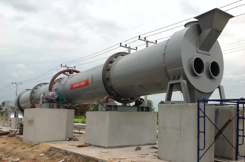
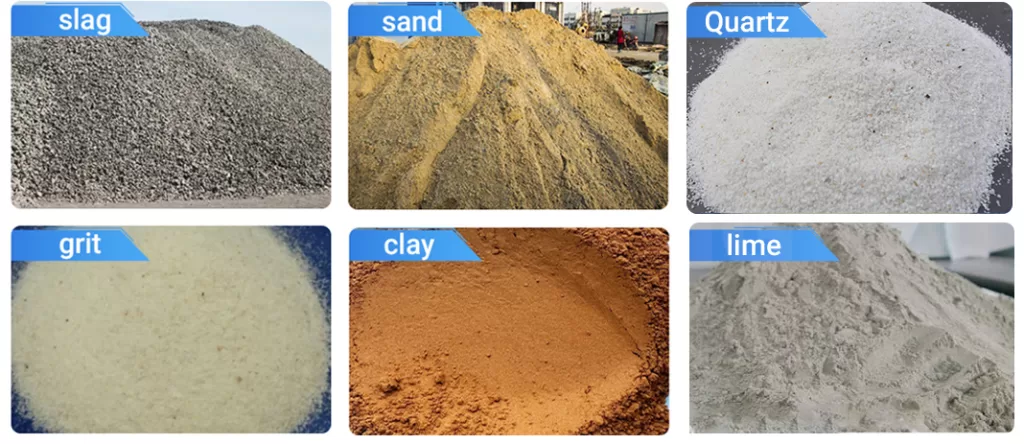
A rotary drum dryer is essentially a rotating cylinder that uses hot gas to dry bulk materials fed into it. In mineral processing, it dries ores, concentrates, coal, sand, and limestone, improving handling, storage, and downstream process efficiency.
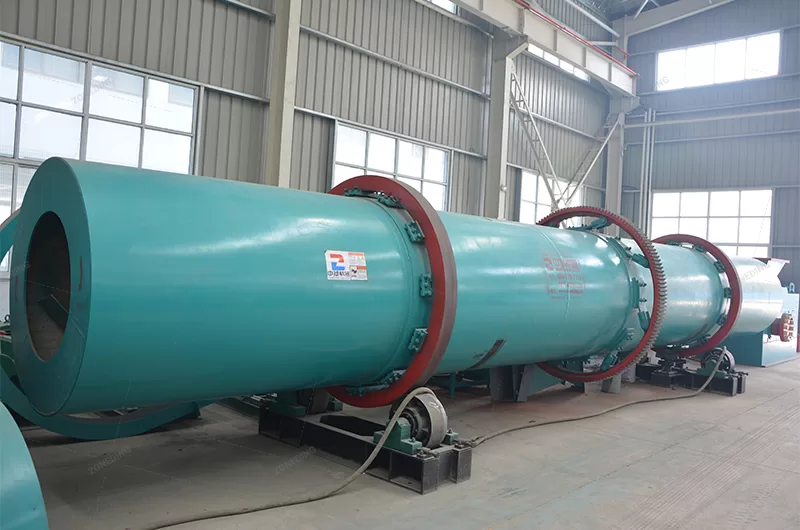
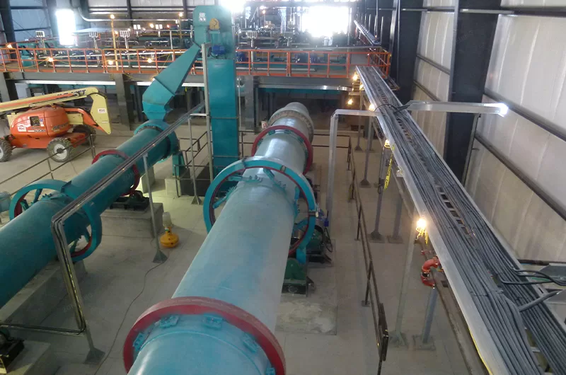
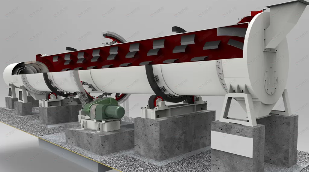
Rotary dryers are fundamental in many industrial processes, especially where bulk materials need moisture reduction. They consist of several key parts working together. The main body is a large, cylindrical shell, slightly inclined to help material flow from the feed end to the discharge end as it rotates. Inside the shell, lifters (or flights) are attached. These pick up the material and shower it down through the stream of hot gas passing through the drum. A drive system rotates the drum at a controlled speed. A heat source (like a burner using gas, oil, or coal) generates the hot gas, and fans manage the airflow. Seals at both ends minimize air leakage and dust escape. In mineral processing, their role is critical. They prepare materials for smelting, further concentration, screening, or simply make them easier and cheaper to transport. Dry material flows better, prevents freezing or clumping, and meets quality specifications for sale or subsequent processes.
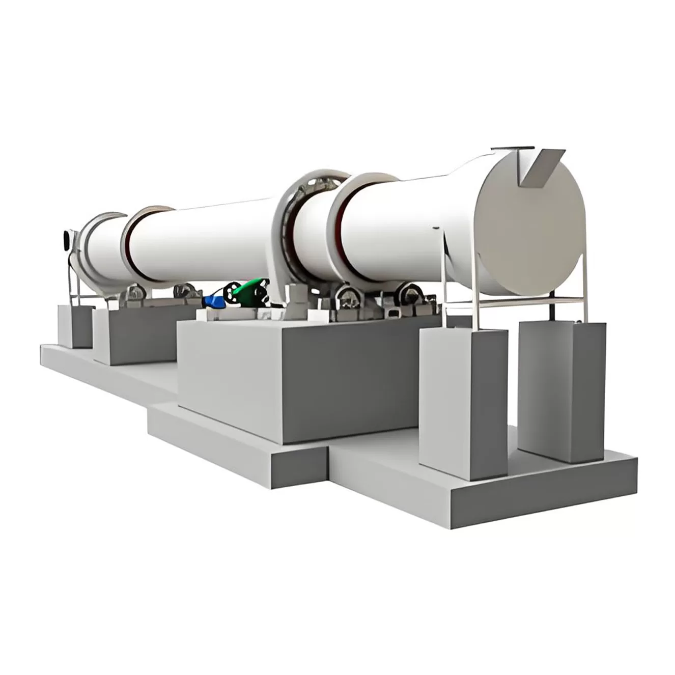
Drum Shell: The main rotating cylinder.
Lifters (Flights): Internal plates lifting and showering material.
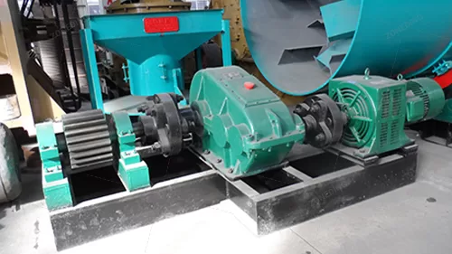
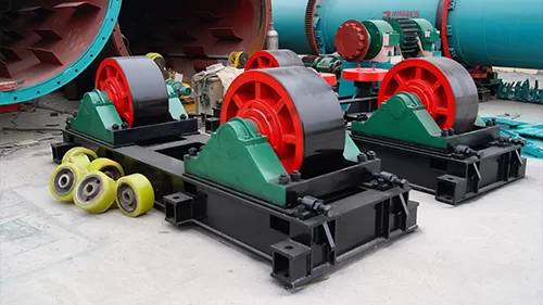
Drive System: Motor, gearbox, and support rollers (trunnions) to rotate the drum.
Heat Source: Burner or furnace providing hot gas.
Feed and Discharge Chutes: Introduce wet material and remove dry product.
Seals: Minimize air leakage at feed and discharge ends.
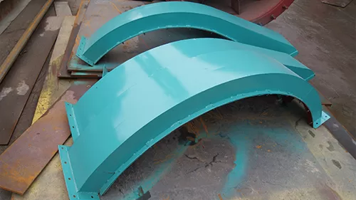
Support Structure: Frame holding the drum and drive.
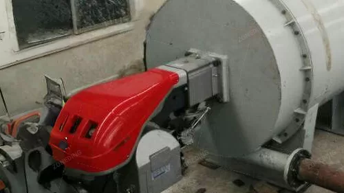
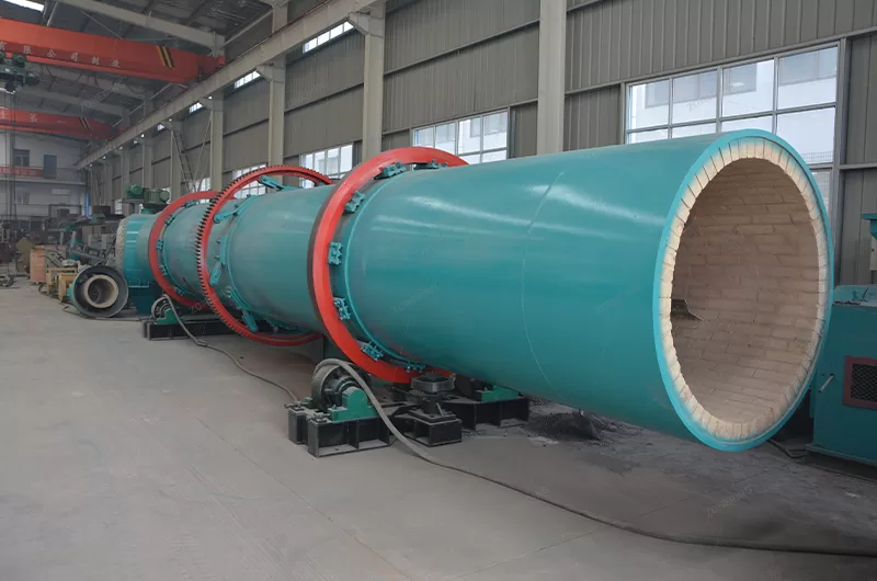
It works by lifting material with internal flights and showering it through hot gas flowing inside the drum. Direct contact (convection) and heat from the drum shell (conduction/radiation) evaporate the moisture effectively.
The process relies on maximizing contact between the wet material and the hot drying medium (usually air or flue gas). As the drum rotates, the internal lifters pick up the material along the bottom. When the lifters reach a certain angle, the material cascades, or showers, down through the interior volume of the drum. This showering action creates a “curtain” of material. The hot gas flows through this curtain, transferring heat directly to the particles primarily through convection. This is the most significant mode of heat transfer in most direct-heat rotary dryers. Additionally, heat is transferred to the material when it’s in contact with the hot drum shell (conduction) and through heat radiating from the hot gas and the shell itself (radiation). The heat absorbed by the material increases the vapor pressure of the water it contains. When the vapor pressure exceeds that of the surrounding air, the water evaporates and is carried away by the airflow. The efficiency of this process depends heavily on how well the lifters create the material curtain and how effectively the hot gas flows through it.
The design and arrangement of lifters are critically important for drying efficiency, maybe even more so than just the gas temperature. Good lifter design maximizes the material curtain, ensuring good gas-solid contact. Poor design lets gas bypass the material, wasting huge amounts of energy. Different materials need different lifter designs. Sticky materials need designs that prevent build-up, while fragile materials need gentle lifting. Worn or missing lifters drastically cut heat transfer, even if temperature readings seem okay. We always emphasize calculating lifter design based on the specific material’s properties.
The effectiveness depends on the gas velocity, temperature, and humidity, as well as the material’s residence time inside the dryer. The goal is to provide enough heat and time to remove the desired amount of moisture without overheating the material.
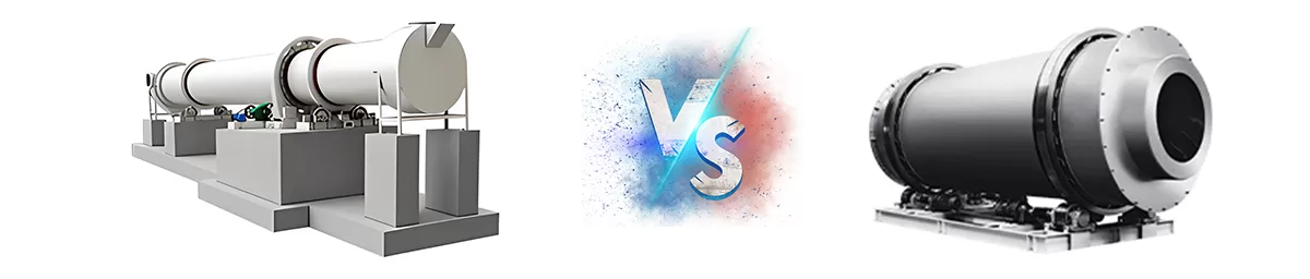
| Single Drum Dryer | Three Drum Dryer | |
| Diameter of Outer Cylinder(m) | 1.2-3.6 | 2.5-3.6 |
| Length(m) | 8.0-28.0 | 7.0-8.0 |
| Volume(m³) | 9.0-285.0 | 16.63-81.38 |
| Capacity(T/H) | 1.9-76.0 | Yellow Sand:25-70 Slag: 20-65 |
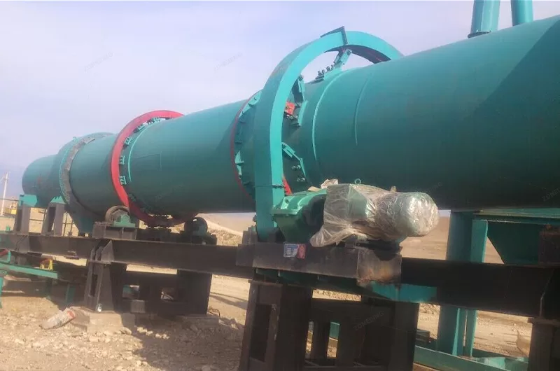
There are types of drum dryer like single drum dryer, double drum one, three-drum one, and air-flow dryer, etc. Two of mostly used drying machines are compared here. Hope it arises a little help. From this table, it is clear that:
1> Three Drum Dryer takes less space but a better utilization of the heat;
2> Three Drum Dryer is of lower energy consumption than a single drum dryer when they take the same space;
3> Single Drum Dryer is of larger capacity and lower price;
4> Single Drum Dryer is easier operated and maintained.
Direct dryers mix hot gas directly with the material being dried. Indirect dryers heat the drum shell externally, keeping the heating medium separate from the material. Choose direct for robust materials; indirect for heat-sensitive or contamination-averse ones.
%Comparison diagram of direct vs indirect dryer
The key distinction lies in how heat is delivered to the material. In a direct-heat rotary dryer, the hot gases produced by a burner or furnace flow directly through the drum in contact with the material. This allows for very efficient heat transfer (mostly convection), making direct dryers generally more thermally efficient and often less expensive initially. They are suitable for materials that are not heat-sensitive and won’t be contaminated or negatively affected by the products of combustion (like ores, coal, sand, limestone).
In an indirect-heat rotary dryer, the rotating drum is enclosed in an outer shell or heated externally by a furnace or steam jacket. The heat transfers through the drum shell wall to the material inside (mostly conduction and radiation). The drying atmosphere inside the drum can be air or an inert gas, which doesn’t mix with the combustion gases. This design is used when the material must not contact combustion products, is very fine and might get carried away by high gas flow, is heat-sensitive, or needs to be dried in a controlled atmosphere. Indirect dryers are typically less thermally efficient and have higher capital costs but offer product purity and protection.
Within direct dryers, gas flow relative to material flow is also crucial. Counter-current flow (hot gas enters at the discharge end, material at the feed end) is usually the most thermally efficient because the hottest gas meets the driest material, maximizing the temperature difference along the dryer length. Co-current flow (gas and material enter the same end) exposes the wettest material to the hottest gas. This provides faster initial drying and a lower exit temperature for the material, which is better for heat-sensitive products. Co-current flow can also be safer for materials with explosion risks (like fine coal) because the initial moisture cools the hot gas inlet area. Don’t just default to counter-current for efficiency; consider material sensitivity and safety first.
| Feature | Direct Heat Dryer | Indirect Heat Dryer |
|---|---|---|
| Heat Transfer | Hot gas directly contacts material | Heat transfers through the drum shell |
| Efficiency | Generally Higher Thermal Efficiency | Generally Lower Thermal Efficiency |
| Contamination | Risk of contact with combustion products | No contact with combustion products |
| Product Suitability | Robust, non-sensitive materials (ores, coal) | Heat-sensitive, contamination-risk, fine materials |
| Gas Flow | High volume, carries away moisture | Lower internal gas flow, separate heating medium |
| Initial Cost | Generally Lower | Generally Higher |
| Complexity | Simpler design | More complex construction (outer shell/jacket) |
Choosing depends entirely on your material’s properties and process requirements.
| Spec./m (Dia.×Length) | Shell Cubage (m³) | Capacity (t/h) | Installation Obliquity(%) | Highest Inlet Air Temperature(℃) | Main Motor (kw) | Weight (t) |
| Φ1.2×8.0 | 9.0 | 1.9~2.4 | 3~5 | 700~800 | 7.5 | 9 |
| Φ1.2×10 | 11.3 | 2.4~3.0 | 3~5 | 700~800 | 7.5 | 11 |
| Φ1.5×12 | 21.2 | 4.5~5.7 | 3~5 | 700~800 | 15 | 18.5 |
| Φ1.5×14 | 24.7 | 5.3~6.6 | 3~5 | 700~800 | 15 | 19.7 |
| Φ1.5×15 | 26.5 | 5.7~7.1 | 3~5 | 700~800 | 15 | 20.5 |
| Φ1.8×12 | 30.5 | 6.5~8.1 | 3~5 | 700~800 | 18.5 | 21.5 |
| Φ1.8×14 | 35.6 | 7.6~9.5 | 3~5 | 700~800 | 18.5 | 23 |
| Φ2.2×12 | 45.6 | 9.7~12.2 | 3~5 | 700~800 | 22 | 33.5 |
| Φ2.2×14 | 53.2 | 11.4~14.2 | 3~5 | 700~800 | 22 | 36 |
| Φ2.2×16 | 60.8 | 13.0~16.2 | 3~5 | 700~800 | 22 | 38 |
| Φ2.4×14 | 63.3 | 13.5~16.9 | 3~5 | 700~800 | 37 | 45 |
| Φ2.4×18 | 81.4 | 17.4~21.7 | 3~5 | 700~800 | 37 | 49 |
| Φ2.4×20 | 90.4 | 19.3~24.1 | 3~5 | 700~800 | 45 | 54 |
| Φ2.4×22 | 99.5 | 21.2~26.5 | 3~5 | 700~800 | 45 | 58 |
| Φ2.6×24 | 127.4 | 27.2~34.0 | 3~5 | 700~800 | 55 | 73 |
| Φ3.0×20 | 141.3 | 30.1~37.7 | 3~5 | 700~800 | 75 | 85 |
| Φ3.0×25 | 176.6 | 37.7~47.1 | 3~5 | 700~800 | 75 | 95 |
| Φ3.2×25 | 201 | 42.9~53.6 | 3~5 | 700~800 | 90 | 110 |
| Φ3.6×28 | 285 | 60.8~76.0 | 3~5 | 700~800 | 160 | 135 |
| Shell diameter ×shell Length Items | Inside diameter of outer shell (mm) | Inside diameter of inner shell (mm) | Shell Length (m) | Shell cubage (m³) | Shell obliquity | Lifting blade form | Highest inlet air temperature (℃) | Dimensions (m) |
| Φ1.5×15m | 1500 | 500 | 15 | 20.27 | 3-5% | Lifting form | 850 | 16.2×2.7×2.7 |
| Φ1.5×17m | 17 | 22.97 | 18.2×2.7×2.7 | |||||
| Φ1.5×19m | 19 | 25.68 | 20.0×2.9×2.9 | |||||
| Φ1.8×21m | 1800 | 650 | 21 | 35.91 | 3-5% | Lifting form | 850 | 22.5×2.7×2.7 |
| Φ1.8×23m | 23 | 39.33 | 24.5×2.9×2.9 | |||||
| Φ1.8×25m | 25 | 42.75 | 26.5×2.9×2.9 | |||||
| Φ2.2×21m | 2200 | 800 | 21 | 58.10 | 3-5% | Lifting form | 850 | —- |
| Φ2.2×23m | 23 | 63.61 | ||||||
| Φ2.2×25m | 25 | 69.15 |
Note: Data may change for the improving technology; we reserve the right of changing without notice; Machine performance may vary depending on application; for more details, please chat online with Zonedingengineers.